

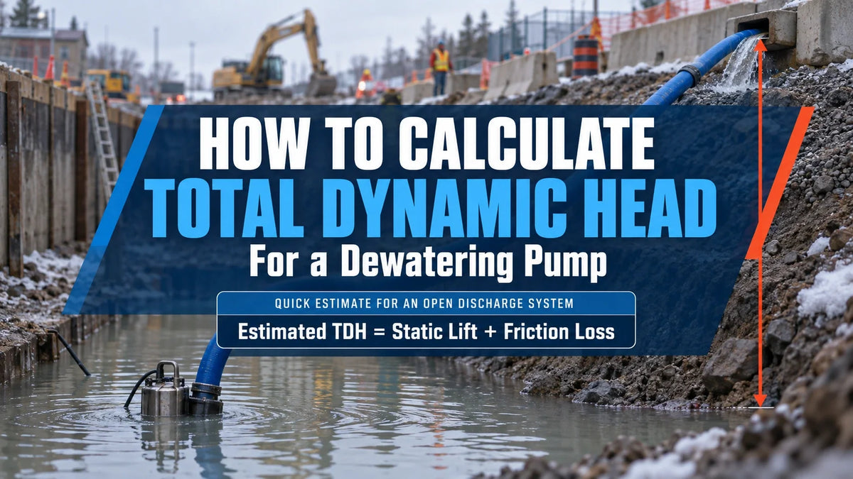
A pump may move plenty of water at ground level and still fall short once you add elevation, a long hose, and several fittings. That is why total dynamic head matters.
Total dynamic head, or TDH, is the head a pump must produce at the flow your job requires. For a quick estimate on many open dewatering systems:
Estimated TDH = Static Lift + Friction Loss
For final selection, add the other applicable losses and check the duty point on the pump curve. Do not choose a pump by horsepower, outlet size, maximum flow, or maximum head alone.
Total Dynamic Head in Simple Terms
A useful pump requirement includes two values:
- Required flow, usually in US gallons per minute (GPM)
- Required total dynamic head, usually in feet
Together, they form the duty point. A job might require 200 GPM at 25 feet of TDH. The pump must deliver both values at the same time.
The TDH Formula
The full energy calculation can be written as:
TDH = Elevation Head + Pressure Head + Velocity-Head Change + Hydraulic Losses
In this guide, a static head means elevation difference. Pressure head is listed separately. Some engineering references combine elevation and pressure difference under static head, so this distinction prevents double-counting.
For two large open bodies of water, both surfaces are at atmospheric pressure, and surface velocities are normally negligible. System head is then mainly the elevation difference plus line and fitting losses. For a free jet at the end of a hose, include outlet velocity head unless the calculation method already accounts for it.
Static Head
Static head is the vertical elevation difference between the source water surface and the discharge point or destination water surface.
Measure from the water surface, not the bottom of a submersible pump. If the pump sits 25 feet below grade but the water surface is 15 feet below the outlet, the static lift is 15 feet.
Use the lowest expected source level and highest discharge condition that can occur together. As an excavation drains, the water surface falls, and static lift usually increases.
Friction Head
Friction head is resistance created as water moves through the hose, pipe, and external components. It depends on flow, actual inside diameter, length, material, condition, and restrictions. When selecting suction and discharge hose, check the actual inside diameter and published friction data rather than relying on nominal size.
Include the full line length. Horizontal hose adds no elevation, but every foot still adds friction. Bends, external strainers, check valves, couplings, and diameter changes may add more loss.
Pressure Head
Pressure head applies when water enters a pressurized main, nozzle, filter, closed tank, or other system that requires pressure. If the destination must maintain a set pressure, a suitable pressure gauge can help confirm the operating condition.
For water:
Pressure Head in Feet = Pressure in PSI x 2.31
The conversion is approximate. For another liquid, divide by its specific gravity. With a free discharge to atmospheric pressure, required outlet gauge pressure is zero.
Velocity Head
Velocity head is the energy carried by moving water. It is often small beside static lift, but it matters when outlet velocity is significant. It can also appear as an exit loss when water enters a larger receiving body.
What to Measure at the Jobsite

Choose the required flow first, then record:
- Highest and lowest expected source water levels
- Discharge elevation or destination water level
- Total suction and discharge line lengths
- Actual hose or pipe inside diameter
- Line material and condition
- External bends, valves, strainers, check valves and couplings
- Open or pressurized discharge condition
- Water condition, including mud, solids, or unusual viscosity
The same hose can have modest loss at low flow and much greater loss at high flow.
Calculate TDH in Five Steps
1. Set the Required Flow
Start with the water volume and available pumping time. If water continues entering the excavation, pump output at the calculated TDH must exceed that inflow for the level to fall.
2. Measure the Static Lift
Measure vertically from the source water surface to the outlet or destination surface. Check the starting and lowest planned levels because the operating condition changes as the pit drains.
3. Calculate Line Friction
Use a friction chart for the actual line at the required flow. If the chart reports loss per 100 feet:
Line Loss = Published Loss per 100 ft x Total Line Length / 100
If the result is in PSI, multiply it by approximately 2.31 to convert it to feet of water. If it is already in feet of head, do not convert it again.
4. Add Minor Losses and Required Pressure
Add losses from external components using published resistance coefficients or equivalent lengths. Then add any required destination pressure. Read the pump-curve notes first so you do not count a loss already included in the tested assembly.
5. Calculate the Duty Point
Add the applicable elevation, pressure, velocity, and friction values. Keep the result tied to the flow used in the friction calculation.

Worked Dewatering Example
This screening example uses:
- Liquid: Water
- Required flow: 200 US GPM
- Static lift: 20 feet
- Hose: 100 feet of 4-inch layflat
- Chart friction: 0.8 PSI per 100 feet
- Assumed hose ID for velocity: 4.00 inches
- Discharge: Free from the hose outlet
- Other external fitting losses: Not yet included
The 0.8 PSI value is from the 4-inch column of a Rivulis layflat friction chart hosted by Rain-Flo. Use the chart for the hose being installed because the inside diameter and construction affect the result.
Convert friction to feet of water:
0.8 PSI x 2.31 = 1.85 feet
At 200 US GPM through an assumed 4.00-inch ID, velocity is about 5.1 feet per second. The corresponding outlet velocity head is approximately 0.41 feet.
Add the known values:
20 + 1.85 + 0.41 = 22.26 feet of TDH
The preliminary duty requirement is about 200 GPM at 22.3 feet of TDH, before external bends, valves, strainers, or other fittings are added.

How Hose Length Changes the Result
At the same flow, increasing the 4-inch hose from 100 to 300 feet triples the chart-based friction:
0.8 PSI x 3 = 2.4 PSI
2.4 PSI x 2.31 = 5.54 feet
With the same lift and velocity head, preliminary TDH becomes about 26.0 feet before other fitting losses. Horizontal distance does not increase static lift, but it can change the operating point.
Use TDH on the Pump Curve
Plot the required flow and head on the candidate pump's performance curve. The actual operating point occurs where the pump curve meets the system curve.
Confirm that the expected point falls within the published operating range. Read the curve notes because some curves exclude losses from check valves, priming systems or accessories.
Check more than one condition when the water level changes. The pump may run at higher flow when the pit is full and lower flow as static lift rises. Both conditions should remain within the allowed range.
- Maximum or runout flow occurs near the lowest head on the curve.
- Shutoff head occurs at zero flow.
Neither value describes normal jobsite output. The Hydraulic Institute pump-curve guide also warns against operation at shutoff or runout.
Common TDH Calculation Mistakes
Most poor selections trace back to a few mistakes:
- Counting only vertical lift and ignoring line friction
- Ignoring horizontal hose because it adds no elevation
- Using nominal hose size without checking inside diameter
- Selecting a pump before setting the required flow
- Expecting maximum GPM and maximum head together
- Using only the starting water level
- Forgetting external valves, bends, or strainers
- Counting suction lift twice on a surface-pump system
- Adding an unsupported safety percentage instead of identifying the uncertainty
For a surface pump, including gas-engine dewatering pumps, include suction-line friction and external suction fittings. But if static elevation is measured from the source water surface to the destination, do not add suction lift a second time.
When the Basic Calculation Is Not Enough
A basic water calculation may not represent systems involving:
- Thick slurry or unusually viscous liquid
- A high concentration of suspended solids
- Long or restrictive surface-pump suction lines
- A pressurized destination
- Several pumps operating together
- Large changes in water level or valve position
Viscosity can change pump head, flow, efficiency, power, and NPSH requirements. Surface pumps also need a separate net positive suction head check. NPSH affects suction performance and cavitation risk, but it is not added to TDH.
If the water contains gravel, leaves, or larger debris, compare the duty point with pumps designed for solids handling in the trash pump collection.
Select the Pump by Its Duty Point
Start with the job, not the largest number on the product page. Set the flow, measure the system, calculate the applicable losses, and check the operating range on the pump curve.
This produces a defensible selection based on expected conditions. Actual hose dimensions, fluid properties, component losses, and curve notes still control the final result.
Frequently Asked Questions
What is the total dynamic head on a dewatering pump?
TDH is the head a pump must produce at a specific flow to overcome elevation, pressure, velocity effects, and hydraulic losses in the complete system.
Does horizontal hose length add to pump head?
Horizontal hose does not add static lift. It does add friction, so include its full length in the TDH calculation.
How do you convert PSI to feet of head?
For water, multiply PSI by approximately 2.31. For another liquid, divide that result by the liquid's specific gravity.
Is the maximum pump head the same as TDH?
No. Maximum or shutoff head occurs at zero flow. TDH is the head required by the actual system at the selected flow.
Have your required flow and TDH? Compare dewatering pumps by performance curve, discharge size, and solids-handling capacity.